Product Code:
RF0023
Description:
RF and Microwave
Specification:
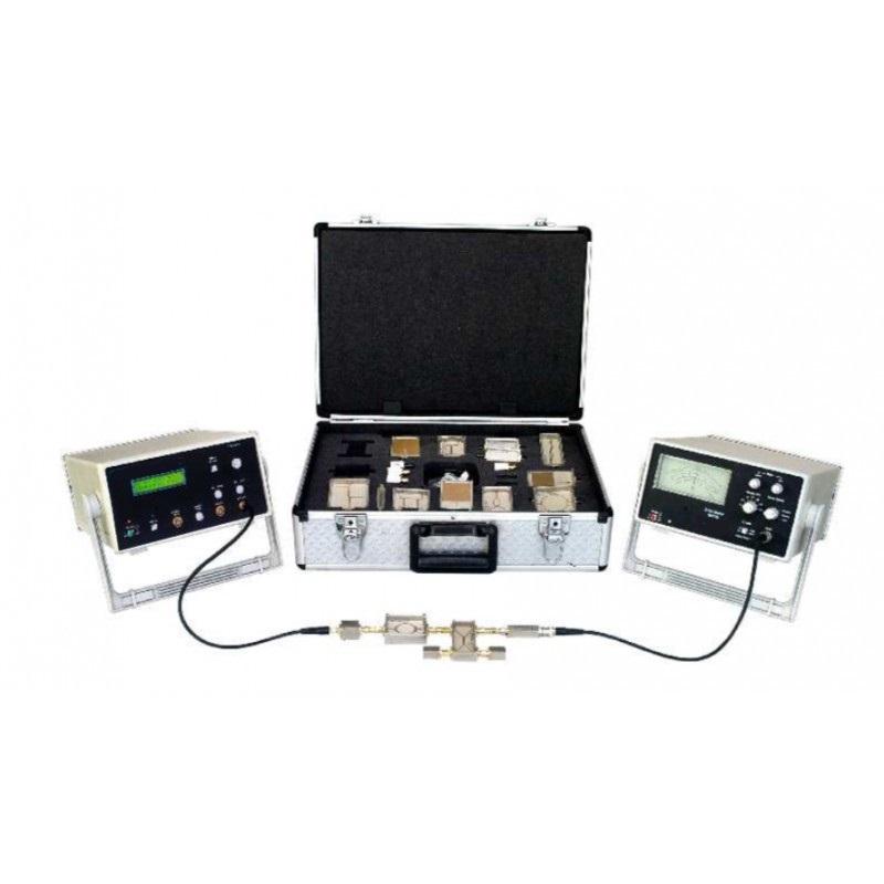
RF AND MICROWAVE -
FEATURES
Actual transmission line provided
Characteristics of transmission line including attenuation, phase delay, matching, frequency response and standing waves
Measurement of attenuation, input impedance and phase displacement
Fault localization within the line
Test signal generator provided
Detailed instruction manual
Set of required patchcords
SPECIFICATIONS
Transmission Lines
Coaxial Cable 100m (25m x 4 )
Impedance matching
0 to 100? variable load (quantity 2), 1? fixed load
Test generator
Sine wave : 10 KHz ~ 4 MHz
Square wave : 10 KHz ~ 4 MHz
Interconnections
4mm sockets on all input / output connections
Test Points
10 Test Points
On-board circuit mimic
Illustrates functional blocks for ease of experimentation
Power Requirement
Power Requirement
EXPERIMENTS
Measuring the characteristics of an actual transmission line such as R, L, C, G, Zo, for different lengths of transmissions Line
Measuring the attenuation of a transmission line for different lengths of the transmission line for
Open ended line
Short ended line
Matched line
Measuring the Input Impedance of the line under different load conditions such as,
Line terminated with matched load
Open line
Short circuited line
Measuring phase displacement between the current and voltage at input of line for different load conditions
Line terminated with matched load;
Open line
Short circuited line
FEATURES:
Separate modules for oscillators, RF amplifier with AGC, IF amplifier with AGC, filters and double balanced mixer.
Adjustable coil for IF, RF curves adjustment.
Separate coil kit consisting of ferrite cores, coil formers and enameled wires.
Connector, cables and power module for interconnections.
Comprehensive manual.
SPECIFICATIONS:
RF Filter Module
RF notch filter.
Chebyshev 7th order RF low pass filter.
Chebyshev 7th order RF high pass filter.
Top Ccoupled 3rd order Chebyshev band pass filter.
RF Mixer Module.
RF Oscillator Module
FET RFO scillator.
80MHz ~ 110MHz Hartley VCO.
RF Amplifier Module
CH4RF Amplifier with AGC.
MOSFET gain control.
IF amplifier module with AGC.
10MHZ crystal RF oscillato rmodule.
EXPERIMENTS:
RF Filter
Study of RF notch filter.
Study the effect of ferrite rod when passed through the center of the coil.
Study of RF low pass filter.
Study of RF high pass filter.
Study of RF band pass filter.
Study of RF stagger tuning with the help of loose coupled notch filter.
Study the effect of tighter coupling by introducing ferrite rod in the coils.
Observe the effect of trimmer capacitor on the filter response.
RF Mixer
Study the RF mixer parameters like mixed output, compression, Inter-modulation, ConversionLoss etc..
RF Oscillator
Study of FETRFoscillator.
Study of 80MHz ~ 110MH Hartley VCO.
Study of harmonics.
Study of variableoscillator.
RF Amplifier
Study of CH4RF Amplifier with AGC gain control.
MOSFET gain control design.
Effect of Peaking and Band Pass in relation with the gain by adjusting the coil.
Effect of AGC on output saturation due to excessive input.
IF Amplifier
Study of IF Amplifier with AGC.
Study the effect of coil adjustment on IF curves.
Effect of AGC on output saturation due to excessive input.
IF Oscillator
Studyof10MHZ crystalRFoscillator design.
Study of harmonics.
Effect of trimmer capacitor and coil adjustment for optimum outpu