Product Code:
RF0026
Description:
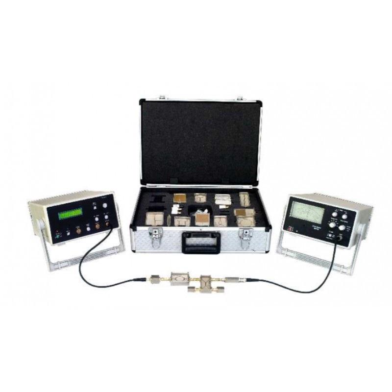
Advanced Microstrip Component Trainer
Specification:
ADVANCED MICROSTRIP COMPONENT TRAINER -
FEATURES:
MCT-A training system enables students to understand the basic structure of the radio frequency system its working principle, simulation analysis, test equipment and measurement skills.
MCT-A uses radio frequency modular training systems for experiments in structural design.
While this training system provides a very simple and flexible assembly, it is integrated in an easy-to-carry and portable box.
SPECIFICATIONS:
VCO
F=1300 ~ 2350MHz.
Po >= 5dBm.
Adjustable voltage : 0V ~ 20V.
Matching Load
50 Ohm Matching Load : 50 Ohm ~ 100 Ohm.
1/4 Wavelength matching.
Load : 50 Oham ~ 100 + j80 Oham.
Microstrip Ring
Fo = 2000 MHz ± 50 MHz.
delta F >= 400 MHz .
Insertion loss L <= 3dB.
Insertion Loss I >= 15dB .
Microstrip Ring
Single - directional coupling.
Fo = 2000 MHz ± 50 MHz .
delta F >= 800 MHz .
C = 10 ± 1 dB .
D >= 10 dB .
Directional Couplers
Use PIN diodes.
F = 750MHz ~ 2500 MHz.
Insertion loss.
L = 3dBm.
i.e. 1 election for the choice of 2.
PINRF Switching
1 KHz square .
Wave modulation : 30 % ~ 90 %.
PIN Modulator
Fo = 2000 ± 50 MHz.
Insertion loss L <= 7 dB.
delta F >= 30 MHz .
Round Resonator
Fo = 2100 ± 50 MHz .
delta F > = 450 MHz .
[ S /delta >= 20 dB ] .
[ S /delta >= 20 dB ] .
[ S /delta >= 20 dB ] .
Hybrid Ring
F = 1960 ± 30 MHz.
G > = 5 dB .
delta F = 40 MHz .
Mixer
RF/ LO : F = 200 MHz ~ 3000 MHz.
IF = 50 MHz ~ 1000 MHz .
Loss L <= 12 dB(PLO >= 7 dBm ).
Branch Coupler
Fo = 2050 ± 50 MHz.
delta F >= 300 MHz.
D >= 12dB.
RF Amplifiers
F = 50MHz ~ 3000 MHz.
G >= 10 dB.
NF <= 4 dB.
Power distributor
F = 0 MHz ~ 3000 MHz.
Effective bandwith.
delta F = 1000 MHz ~ 3000 MHz .
I >= 10 dB.
Coaxial detector
F = 0.5 GHz ~ 3 GHz.
Sensitivity = 0.15 mV/mW.
Voltage standing wave ratio=1.7.
Frequency response = 0.6 dB.
Attenuator
T / Pi-type : F : 1000 MHz ~ 2500 MHz.
L=10 ± 1 dB.
Mismatch load
OPEN, SHORT : 200 Oham.
Mismatch load.
Measuring line
Microstrip line structure.
Move distance >= 170 mm.
The remaining standing.
Wave ratio <= 1.05.
Microstrip antennas
LPF : delta F = 0 MHz ~ 2100 MHz.
± 50 MHz L < = 1.5 dB.
BPF : Fo = 1950 ± 50 MHz.
delta F < = Fo*15 % MHz.
HPF: F > = 1800 ± 50 MHz.
L < = 1dB.
BSF: Fo = 1800 ± 50 MHz.
delta F> = 600 MHz [ L >= 25dB ].
delta F< = 1500 MHz [ L <= 3dB ].
EXPERIMENTS:
Familiarize with VCO working principle and get to know their performance.
Understanding mixer principle and the work of the main characteristics.
Understanding the basic principles of microstrip ring.
Learn how to use spectrum analyzer to do microstrip ring test.
Grasp the basic principles and methods of directional coupler.
Grasp the principles and methods of impedance matching.
Grasp the principles and methods of impedance mismatching and learn impedance mismatching.
Grasp test theory of power splitter distributor.
Understanding the structure theory, frequency characteristics of hybrid ring.
Get familiar with the inter-relationship between the various ports and hybrid ring Understanding the basic principles of PIN switch and the use of PIN switch.
Grasp the AM, FM principle and understanding AM, FM circut.